Datasheet ADIS16490 (Analog Devices)
| Производитель | Analog Devices |
| Описание | Tactical Grade, Six Degrees of Freedom Inertial Sensor |
| Страниц / Страница | 37 / 1 — Tactical Grade, Six Degrees of Freedom. Inertial Sensor. Data Sheet. … |
| Версия | C |
| Формат / Размер файла | PDF / 1.1 Мб |
| Язык документа | английский |
Tactical Grade, Six Degrees of Freedom. Inertial Sensor. Data Sheet. ADIS16490. FEATURES. GENERAL DESCRIPTION
Модельный ряд для этого даташита
Текстовая версия документа
Tactical Grade, Six Degrees of Freedom Inertial Sensor Data Sheet ADIS16490 FEATURES GENERAL DESCRIPTION Triaxial, digital gyroscope, ±100°/sec dynamic range
The ADIS16490 is a complete inertial system that includes a
±0.05° axis to axis misalignment error
triaxis gyroscope and a triaxis accelerometer. Each inertial sensor
±0.25° axis to package misalignment error
in the ADIS16490 combines industry leading iMEMS® technology
1.8°/hr in run bias stability
with signal conditioning that optimizes dynamic performance.
0.09°/√hr angular random walk
The factory calibration characterizes each sensor for sensitivity,
Triaxial, digital accelerometer, ±8 g
bias, alignment, and linear acceleration (gyroscope bias). As a
3.6 μg in run bias stability
result, each sensor has its own dynamic compensation formulas that
Triaxial, delta angle and delta velocity outputs
provide accurate sensor measurements.
Factory calibrated sensitivity, bias, and axial alignment
The ADIS16490 provides a simple, cost effective method for
Calibration temperature range: −40°C to +85°C
integrating accurate, multiaxis inertial sensing into industrial
Serial peripheral interface (SPI) compatible
systems, especially when compared with the complexity and
Programmable operation and control
investment associated with discrete designs. All necessary motion
Automatic and manual bias correction controls
testing and calibration are part of the production process at
4 finite impulse response (FIR) filter banks,
the factory, greatly reducing system integration time. Tight
120 configurable taps
orthogonal alignment simplifies inertial frame alignment in
Digital input/output (I/O): data ready, external clock
navigation systems. The SPI and register structure provide a
Sample clock options: internal, external, or scaled
simple interface for data collection and configuration control.
On demand self test of inertial sensors Single-supply operation: 3.0 V to 3.6 V
The ADIS16490 uses the same footprint and connector system as
2000 g shock survivability
the ADIS16375, ADIS16480, ADIS16485, and ADIS16488A, which
Operating temperature range: −40°C to +105°C
greatly simplifies the upgrade process. The ADIS16490 is packaged in a module that is approximately 47 mm × 44 mm × 14 mm
APPLICATIONS
and includes a standard connector interface.
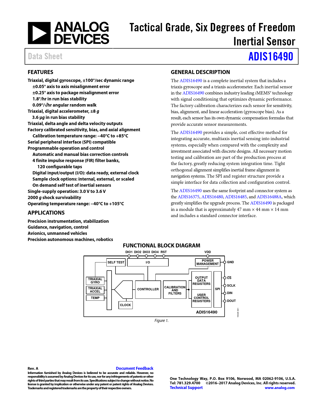
Precision instrumentation, stabilization Guidance, navigation, control Avionics, unmanned vehicles Precision autonomous machines, robotics FUNCTIONAL BLOCK DIAGRAM DIO1 DIO2 DIO3 DIO4 RST VDD POWER SELF TEST I/O GND MANAGEMENT OUTPUT TRIAXIAL CS DATA GYRO REGISTERS SCLK TRIAXIAL CALIBRATION CONTROLLER SPI ACCEL AND FILTERS DIN USER TEMP CONTROL REGISTERS DOUT CLOCK ADIS16490
001 15029- Figure 1.
Rev. A Document Feedback Information furnished by Analog Devices is believed to be accurate and reliable. However, no responsibility is assumed by Analog Devices for its use, nor for any infringements of patents or other rights of third parties that may result from its use. Specifications subject to change without notice. No One Technology Way, P.O. Box 9106, Norwood, MA 02062-9106, U.S.A. license is granted by implication or otherwise under any patent or patent rights of Analog Devices. Tel: 781.329.4700 ©2016–2017 Analog Devices, Inc. All rights reserved. Trademarks and registered trademarks are the property of their respective owners. Technical Support www.analog.com
Document Outline FEATURES APPLICATIONS GENERAL DESCRIPTION FUNCTIONAL BLOCK DIAGRAM REVISION HISTORY SPECIFICATIONS TIMING SPECIFICATIONS Register Specific Stall Times Timing Diagrams ABSOLUTE MAXIMUM RATINGS THERMAL RESISTANCE ESD CAUTION PIN CONFIGURATION AND FUNCTION DESCRIPTIONS TYPICAL PERFORMANCE CHARACTERISTICS THEORY OF OPERATION INERTIAL SENSOR SIGNAL CHAIN Gyroscope Data Sampling Accelerometer Data Sampling External Clock Options Inertial Sensor Calibration Gyroscope Factory Calibration Accelerometer Factory Calibration Filtering REGISTER STRUCTURE SERIAL PERIPHERAL INTERFACE DATA READY READING SENSOR DATA DEVICE CONFIGURATION Dual Memory Structure USER REGISTER MEMORY MAP USER REGISTER DEFINTIONS Page Number (PAGE_ID) Data/Sample Counter (DATA_CNT) Status/Error Flag Indicators (SYS_E_FLAG) Self Test Error Flags (DIAG_STS) Internal Temperature (TEMP_OUT) GYROSCOPE DATA X-Axis Gyroscope (X_GYRO_LOW, X_GRYO_OUT) Y-Axis Gyroscope (Y_GYRO_LOW, Y_GYRO_OUT) Z-Axis Gyroscope (Z_GYRO_LOW, Z_GYRO_OUT) Gyroscope Resolution ACCELERATION DATA X-Axis Accelerometer (X_ACCL_LOW, X_ACCL_OUT) Y-Axis Accelerometer (Y_ACCL_LOW, Y_ACCL_OUT) Z-Axis Accelerometer (Z_ACCL_LOW, Z_ACCL_OUT) Accelerometer Resolution DELTA ANGLES X-Axis Delta Angle (X_DELTANG_LOW, X_DELTANG_OUT) Y-Axis Delta Angle (Y_DELTANG_LOW, Y_DELTANG_OUT) Z-Axis Delta Angle (Z_DELTANG_LOW, Z_DELTANG_OUT) Delta Angle Resolution DELTA VELOCITY X-Axis Delta Velocity (X_DELTVEL_LOW, X_DELTVEL_OUT) Y-Axis Delta Velocity (Y_DELTVEL_LOW, Y_DELTVEL_OUT) Z-Axis Delta Velocity (Z_DELTVEL_LOW, Z_DELTVEL_OUT) Delta Velocity Resolution Product Identification, PROD_ID CALIBRATION Calibration, Gyroscope Scale, X_GYRO_SCALE Calibration, Gyroscope Scale, Y_GYRO_SCALE Calibration, Gyroscope Scale, Z_GYRO_SCALE Calibration, Accelerometer Scale, X_ACCL_SCALE Calibration, Accelerometer Scale, Y_ACCL_SCALE Calibration, Accelerometer Scale, Z_ACCL_SCALE Calibration, Gyroscope Bias, XG_BIAS_LOW, XG_BIAS_HIGH Calibration, Gyroscope Bias, YG_BIAS_LOW, YG_BIAS_HIGH Calibration, Gyroscope Bias, ZG_BIAS_LOW, ZG_BIAS_HIGH Calibration, Accelerometer Bias, XA_BIAS_LOW, XA_BIAS_HIGH Calibration, Accelerometer Bias, YA_BIAS_LOW, YA_BIAS_HIGH Calibration, Accelerometer Bias, ZA_BIAS_LOW, ZA_BIAS_HIGH Scratch Registers, USER_SCR_x Flash Memory Endurance Counter, FLSHCNT_LOW, FLSHCNT_HIGH Global Commands, GLOB_CMD Software Reset Factory Calibration Restore Flash Memory Update On Demand Self Test (ODST) Bias Correction Update Auxiliary I/O Line Configuration, FNCTIO_CTRL Data Ready Indicator Input Sync/Clock Control General-Purpose I/O Control, GPIO_CTRL Miscellaneous Configuration, CONFIG Point of Percussion Linear Acceleration on Effect on Gyroscope Bias Decimation Filter, DEC_RATE Data Update Rate in External Sync Modes Continuous Bias Estimation (CBE), NULL_CNFG Scaling the Input Clock (PPS Mode), SYNC_SCALE FIR Filter Control, FILTR_BNK_0, FILTR_BNK_1 Firmware Revision, FIRM_REV Firmware Revision Day and Month, FIRM_DM Firmware Revision Year, FIRM_Y Boot Revision Number, BOOT_REV Continuous SRAM Testing Signature CRC, Calibration Values, CAL_SIGTR_LWR Signature CRC, Calibration Values, CAL_SIGTR_UPR Derived CRC, Calibration Values, CAL_DRVTN_LWR Derived CRC, Calibration Values, CAL_DRVTN_UPR Signature CRC, Program Code, CODE_SIGTR_LWR Signature CRC, Program Code, CODE_SIGTR_UPR Derived CRC, Program Code, CODE_DRVTN_LWR Derived CRC, Program Code, CODE_DRVTN_UPR Lot Specific Serial Number, SERIAL_NUM FIR FILTERS FIR Filter Bank A, FIR_COEF_A000 to FIR_COEF_A119 FIR Filter Bank B, FIR_COEF_B000 to FIR_COEF_B119 FIR Filter Bank C, FIR_COEF_C000 to FIR_COEF_C119 FIR Filter Bank D, FIR_COEF_D000 to FIR_COEF_D119 Default Filter Performance APPLICATIONS INFORMATION MOUNTING BEST PRACTICES PREVENTING MISINSERTION EVALUATION TOOLS Breakout Board, ADIS16IMU1/PCBZ PC-Based Evaluation, EVAL-ADIS2 POWER SUPPLY CONSIDERATIONS PACKAGING AND ORDERING INFORMATION OUTLINE DIMENSIONS ORDERING GUIDE

 аккумуляторов")


