Datasheet ATtiny11, ATtiny12 - Summary (Atmel)
| Производитель | Atmel |
| Описание | 8-bit AVR Microcontroller with 1K Byte Flash |
| Страниц / Страница | 15 / 1 — Features. Utilizes the AVR. RISC Architecture. High-performance and … |
| Формат / Размер файла | PDF / 235 Кб |
| Язык документа | английский |
Features. Utilizes the AVR. RISC Architecture. High-performance and Low-power 8-bit RISC Architecture
Модельный ряд для этого даташита
Текстовая версия документа
Features
•
Utilizes the AVR
®
RISC Architecture
•
High-performance and Low-power 8-bit RISC Architecture – 90 Powerful Instructions – Most Single Clock Cycle Execution – 32 x 8 General Purpose Working Registers – Up to 8 MIPS Throughput at 8 MHz
•
Nonvolatile Program and Data Memory – 1K Byte of Flash Program Memory In-System Programmable (ATtiny12) Endurance: 1,000 Write/Erase Cycles (ATtiny11/12) – 64 Bytes of In-System Programmable EEPROM Data Memory for ATtiny12 8-bit Endurance: 100,000 Write/Erase Cycles – Programming Lock for Flash Program and EEPROM Data Security Microcontroller
•
Peripheral Features – Interrupt and Wake-up on Pin Change with 1K Byte – One 8-bit Timer/Counter with Separate Prescaler – On-chip Analog Comparator – Programmable Watchdog Timer with On-chip Oscillator Flash
•
Special Microcontroller Features – Low-power Idle and Power-down Modes – External and Internal Interrupt Sources – In-System Programmable via SPI Port (ATtiny12) ATtiny11 – Enhanced Power-on Reset Circuit (ATtiny12) – Internal Calibrated RC Oscillator (ATtiny12) ATtiny12
•
Specification – Low-power, High-speed CMOS Process Technology – Fully Static Operation
•
Power Consumption at 4 MHz, 3V, 25°C Summary – Active: 2.2 mA – Idle Mode: 0.5 mA – Power-down Mode: <1 µA
•
Packages – 8-pin PDIP and SOIC
•
Operating Voltages – 1.8 - 5.5V for ATtiny12V-1 – 2.7 - 5.5V for ATtiny11L-2 and ATtiny12L-4 – 4.0 - 5.5V for ATtiny11-6 and ATtiny12-8
•
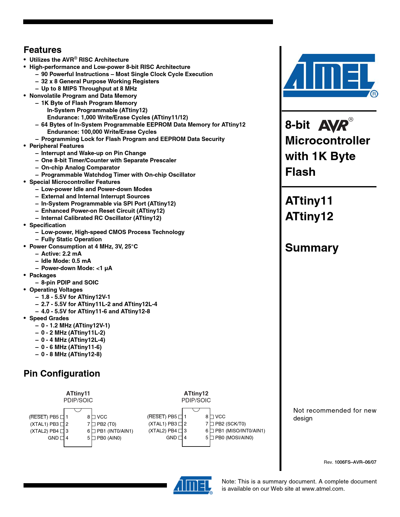
Speed Grades – 0 - 1.2 MHz (ATtiny12V-1) – 0 - 2 MHz (ATtiny11L-2) – 0 - 4 MHz (ATtiny12L-4) – 0 - 6 MHz (ATtiny11-6) – 0 - 8 MHz (ATtiny12-8) Pin Configuration ATtiny11 ATtiny12
PDIP/SOIC PDIP/SOIC Not recommended for new (RESET) PB5 1 8 VCC (RESET) PB5 1 8 VCC design (XTAL1) PB3 2 7 PB2 (T0) (XTAL1) PB3 2 7 PB2 (SCK/T0) (XTAL2) PB4 3 6 PB1 (INT0/AIN1) (XTAL2) PB4 3 6 PB1 (MISO/INT0/AIN1) GND 4 5 PB0 (AIN0) GND 4 5 PB0 (MOSI/AIN0) 10 Rev. 06FS– 10 AVR–0 06FS– 6/0 AVR–0 7 6/0 Note: This is a summary document. A complete document
1
is available on our Web site at www.atmel.com. Document Outline Features Pin Configuration Overview ATtiny11 Block Diagram ATtiny12 Block Diagram Pin Descriptions VCC GND Port B (PB5..PB0) XTAL1 XTAL2 RESET Register Summary ATtiny11 Register Summary ATtiny12 Instruction Set Summary Ordering Information ATtiny11 ATtiny12 Packaging Information 8P3 8S2 Datasheet Revision History Rev. 1006F-06/07 Rev. 1006E-07/06 Rev. 1006D-07/03 Rev. 1006C-09/01

 аккумуляторов")


