
Datasheet Texas Instruments LDC1614 — Даташит
| Производитель | Texas Instruments |
| Серия | LDC1614 |
4-channel, 28-bit Inductance-to-Digital Converter with I2C for Inductive Sensing
Datasheets
LDC1612, LDC1614 Multi-Channel 28-Bit Inductance to Digital Converter (LDC) for Inductive Sensing datasheet
PDF, 1.8 Мб, Файл опубликован: 17 ноя 2014
Выписка из документа
Цены
 Купить LDC1614 на РадиоЛоцман.Цены — от 64 до 26 451 ₽ Купить LDC1614 на РадиоЛоцман.Цены — от 64 до 26 451 ₽20 предложений от 13 поставщиков Оценочный модуль, LDC1614 28-битный преобразователь индуктивности в цифровой сигнал, образец катушек | |||
| LDC1614QRGHRQ1 Texas Instruments | 64 ₽ | ||
| LDC1614QRGHRQ1 Texas Instruments | 201 ₽ | ||
| LDC1614QRGHRQ1 Texas Instruments | 216 ₽ | ||
| LDC1614RGHR Texas Instruments | 403 ₽ | ||
Статус
| LDC1614RGHR | LDC1614RGHT | |
|---|---|---|
| Статус продукта | В производстве | В производстве |
| Доступность образцов у производителя | Да | Да |
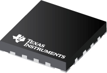
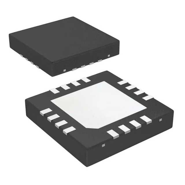
Корпус / Упаковка / Маркировка
| LDC1614RGHR | LDC1614RGHT | |
|---|---|---|
| N | 1 | 2 |
| Pin | 16 | 16 |
| Package Type | RGH | RGH |
| Industry STD Term | WQFN | WQFN |
| JEDEC Code | S-PQFP-N | S-PQFP-N |
| Package QTY | 4500 | 250 |
| Carrier | LARGE T&R | SMALL T&R |
| Маркировка | LDC1614 | LDC1614 |
| Width (мм) | 4 | 4 |
| Length (мм) | 4 | 4 |
| Thickness (мм) | .75 | .75 |
| Pitch (мм) | .5 | .5 |
| Max Height (мм) | .8 | .8 |
| Mechanical Data | Скачать | Скачать |
Параметры
| Parameters / Models | LDC1614RGHR | LDC1614RGHT |
|---|---|---|
| # Input Channels | 4 | 4 |
| Active Supply Current(Typ), мА | 2.1 | 2.1 |
| Analog Supply (V), Max | 2.7 | 2.7 |
| Interface | I2C | I2C |
| L (Inductance) Resolution, Bits | 28 | 28 |
| Рабочий диапазон температур, C | от -40 до 125 | от -40 до 125 |
| Oscillation Amplitude(Max), В | 1.8 | 1.8 |
| Oscillation Amplitude(Min), В | 0.7 | 0.7 |
| Package Group | WQFN | WQFN |
| Package Size: mm2:W x L, PKG | 16WQFN: 16 mm2: 4 x 4(WQFN) | 16WQFN: 16 mm2: 4 x 4(WQFN) |
| Rating | Catalog | Catalog |
| Response Time(Max), 1/fsensor | N/A | N/A |
| Response Time(Min), 1/fsensor | 245 | 245 |
| Rp (Parallel Resonance Impedance) Resolution, Bits | N/A | N/A |
| Sensor Frequency, Hz | 1k to 10M | 1k to 10M |
| Sensor Rp Range(Max), Ohms | 100K | 100K |
| Sensor Rp Range(Min), Ohms | 250 | 250 |
| Stand-By Current(Typ), uA | 35 | 35 |
Экологический статус
| LDC1614RGHR | LDC1614RGHT | |
|---|---|---|
| RoHS | Совместим | Совместим |
Application Notes
- Inductive Sensing Touch-On-Metal Buttons Design GuidePDF, 2.6 Мб, Файл опубликован: 30 мар 2016
- LDC1612 LDC1614 Linear Position SensingPDF, 239 Кб, Файл опубликован: 20 апр 2015
This application note explains how both approaches can be used to determine the position of a target that is moved laterally above the sensor coil and provides system design guidelines for each approach. Resolution calculations are based on the 28-bit devices LDC1612 and LDC1614, but the same principles apply to other LDCs such as LDC1000, LDC1041, LDC1312, and LDC1314. - Power Reduction Techniques for the LDC131x/161x for Inductive SensingPDF, 215 Кб, Файл опубликован: 18 мар 2016
Inductive sensing is a contactless technique for applications ranging from position or motion measurement of a conductive target to detection of spring compression or extension. Depending on the specific application, there are different system requirements regarding sensitivity, responsiveness, and power. Power consumption is a key parameter for many applications, including wearables, consumer ele - Optimizing L Measurement Resolution for the LDC161x and LDC1101PDF, 108 Кб, Файл опубликован: 12 фев 2016
- LDC1xxx LDC Target Design (Rev. A)PDF, 907 Кб, Версия: A, Файл опубликован: 9 май 2017
Texas Instruments’ Inductive-to-Digital Converter (LDC) technology can accurately measure with a wide variety of target sizes, shapes, and material composition. There are several target design guidelines to maximize the effectiveness of an LDC measurement system. This application note covers the relevant factors of target design that affect inductive sensing, and provides guide - LDC1312, LDC1314, LDC1612, LDC1614 Sensor Status MonitoringPDF, 102 Кб, Файл опубликован: 9 окт 2016
TI’s multichannel inductance-to-digital converters (LDCs) LDC1612, LDC1614, LDC1312 and LDC1314feature three different methods for reporting conversion status information including errors, warnings, andcompleted conversion results. Information is available through the data registers, the status registers, andthe INTB pin of the device. This application note explains usage and interpretation - Configuring Inductive-to-Digital-Converters for Parallel Resistance (RP) Variati (Rev. A)PDF, 255 Кб, Версия: A, Файл опубликован: 1 июн 2015
This application note reviews sensor RP configuration for LDC devices. LDC1000, LDC1041, LDC1051, LDC1312, LDC1314, LDC1612, LDC1614 are covered in this note. Clear understanding on how to set the RP_MIN and RP_MAX registers is necessary for not only RP measurements, but also for optimum L measurements. The fundamental principle of RP measurements is that magnetic fields from an LC circuit ge - Setting LDC1312/4, LDC1612/4, and LDC1101 Sensor Drive ConfigurationPDF, 298 Кб, Файл опубликован: 5 апр 2016
- EMI Considerations for Inductive SensingPDF, 151 Кб, Файл опубликован: 22 фев 2017
This application note explains various EMI reduction techniques to help improve EMI performance for TI'sInductance-to-Digital Converters (LDC). Each section details a general technique with references to otheruseful online documents. A list of relevant EMI reduction techniques is provided for specific devices withinthe LDC family of products. - LDC Device Selection Guide (Rev. B)PDF, 360 Кб, Версия: B, Файл опубликован: 21 мар 2017
- LDC Sensor DesignPDF, 1.0 Мб, Файл опубликован: 24 мар 2015
Getting the best performance out of an LDC requires a sensor suitable for the measurement. This app-note covers the parameters to consider when designing a sensor for a specific application. Specific areas of focus include the physical routing characteristics of PCB based sensors, considerations for the sensor capacitor, and techniques to minimize or compensate for parasitic effects. - Measuring Rp of an L-C Sensor for Inductive SensingPDF, 205 Кб, Файл опубликован: 1 окт 2015
When designing an application using TI’s LDC series of inductive sensors, it is necessary to know the L-C sensor’s equivalent parallel resistance RP at the sensor’s resonant frequency. The RP value changes as the target is moved; the minimum RP occurs when the metal target is closest to the sensor. The maximum RP occurs when the target is at the farthest distance. Accordingly, both values should b
Модельный ряд
Серия: LDC1614 (2)
Классификация производителя
- Semiconductors> Sensing Products> Inductive Sensing> Inductance to Digital Converters


