Datasheet P9222-R (IDT) - 27
| Производитель | IDT |
| Описание | Wireless Power Receiver for Low Power Applications |
| Страниц / Страница | 52 / 27 — P9222-R Datasheet 10. Applications Information |
| Версия | 20190927 |
| Формат / Размер файла | PDF / 2.8 Мб |
| Язык документа | английский |
P9222-R Datasheet 10. Applications Information

Модельный ряд для этого даташита
Текстовая версия документа
P9222-R Datasheet 10. Applications Information
The P9222-R is an integrated wireless power receiver for mobile or stationary devices. The device can receive and provide to its output up to
5W of wireless power using near-field magnetic induction. 10.1 Receiver Coil
The following coils are recommended for use in 5W or 3W applications in order to achieve optimum performance with the P9222 receiver.
Table 6. Recommended Coil Manufacturer Output Power Vendor Part Number Inductance at
100kHz Resonant Caps (Cs) DC Resistance at 20℃ 5W SUNLORD MQQRR303008S8R2 8.2µH ± 10% 300nF 180mΩ max 3W TDK WR303050-12F5-ID 8.2µH ± 10% 300nF 280mΩ max 10.2 Series and Parallel Resonant Capacitor Selection
WPC inductive power transmission uses resonant circuits to enhance the inductive power transmission. Especially for systems with a low
coupling factor, a resonant receiver can improve power transfer. The simplified Rx-coil network consists of a series resonant capacitor, C1,
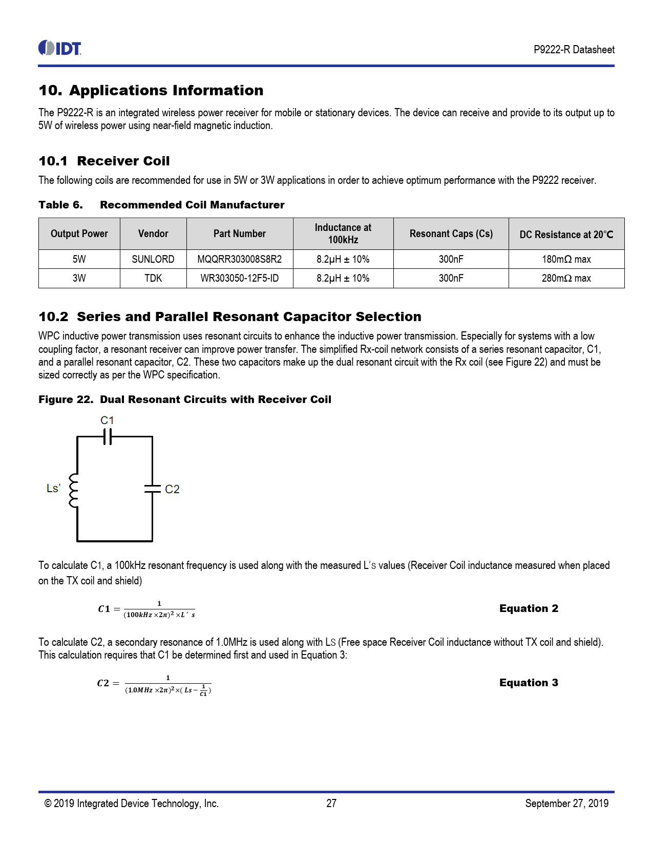
and a parallel resonant capacitor, C2. These two capacitors make up the dual resonant circuit with the Rx coil (see Figure 22) and must be
sized correctly as per the WPC specification.
Figure 22. Dual Resonant Circuits with Receiver Coil To calculate C1, a 100kHz resonant frequency is used along with the measured L′S values (Receiver Coil inductance measured when placed
on the TX coil and shield)
𝑪𝟏 = 𝟏 Equation 2 (𝟏𝟎𝟎𝒌𝑯𝒛 ×𝟐𝝅)𝟐 ×𝑳′𝒔 To calculate C2, a secondary resonance of 1.0MHz is used along with LS (Free space Receiver Coil inductance without TX coil and shield).
This calculation requires that C1 be determined first and used in Equation 3:
𝑪𝟐 = 𝟏
(𝟏.𝟎𝑴𝑯𝒛 ×𝟐𝝅)𝟐 ×( 𝑳𝒔 − Equation 3 𝟏
)
𝑪𝟏 © 2019 Integrated Device Technology, Inc. 27 September 27, 2019
 Купить P9222-RAZGI8 на РадиоЛоцман.Цены — от 226 до 1 455 ₽