Datasheet A6275 (Allegro) - 12
| Производитель | Allegro |
| Описание | 8-Bit Serial Input Constant-Current Latched LED Driver |
| Страниц / Страница | 12 / 12 — Serial-Input Constant-Current Latched LED Driver. A6275. with Open LED … |
| Формат / Размер файла | PDF / 363 Кб |
| Язык документа | английский |
Serial-Input Constant-Current Latched LED Driver. A6275. with Open LED Detection and Dot Correction. Package A 16-Pin DIP
Модельный ряд для этого даташита
Текстовая версия документа
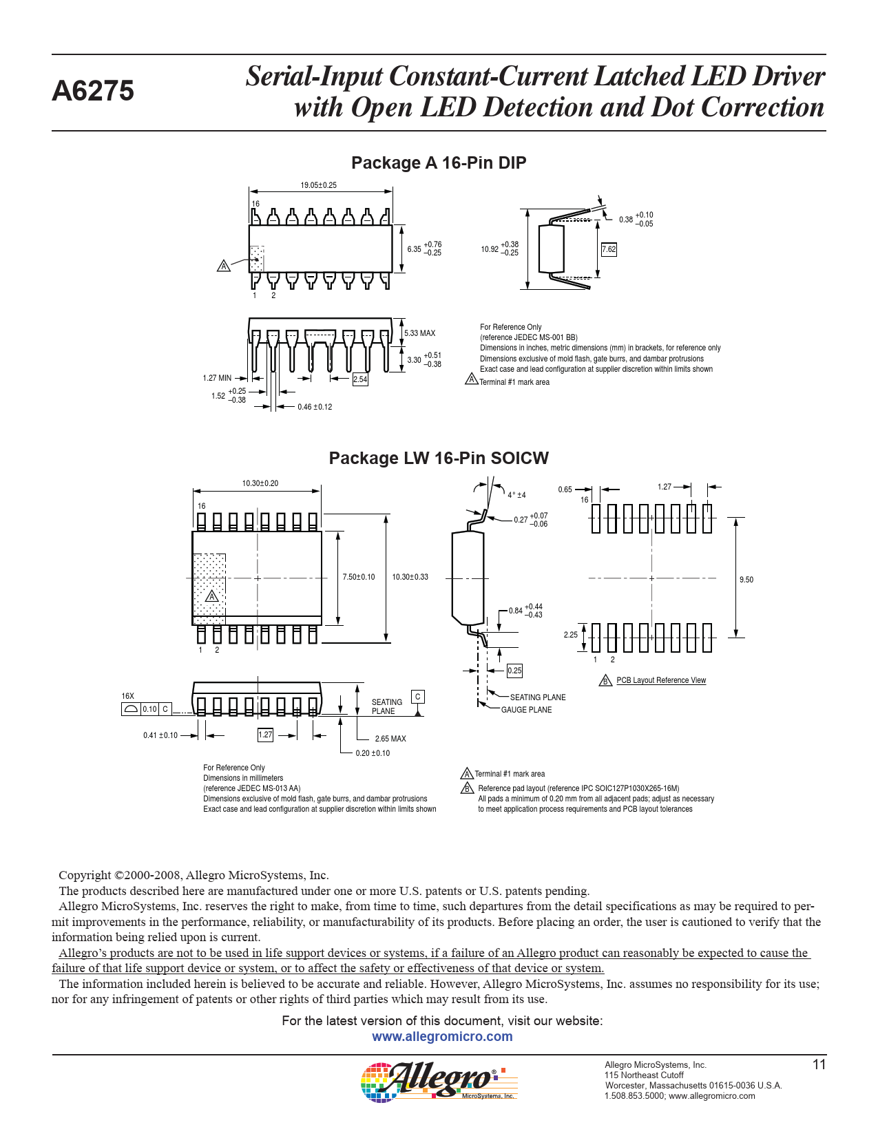
Serial-Input Constant-Current Latched LED Driver A6275 with Open LED Detection and Dot Correction Package A 16-Pin DIP
19.05±0.25 16 0.38 +0.10 –0.05 6.35 +0.76 –0.25 10.92 +0.38 –0.25 7.62 A 1 2 For Reference Only 5.33 MAX (reference JEDEC MS-001 BB) Dimensions in inches, metric dimensions (mm) in brackets, for reference only 3.30 +0.51 Dimensions exclusive of mold flash, gate burrs, and dambar protrusions –0.38 Exact case and lead configuration at supplier discretion within limits shown 1.27 MIN 2.54 A Terminal #1 mark area 1.52 +0.25 –0.38 0.46 ±0.12
Package LW 16-Pin SOICW
10.30±0.20 0.65 1.27 4° ±4 16 16 0.27 +0.07 –0.06 7.50±0.10 10.30±0.33 9.50 A 0.84 +0.44 –0.43 2.25 1 2 1 2 0.25 B PCB Layout Reference View 16X C SEATING PLANE SEATING 0.10 C PLANE GAUGE PLANE 0.41 ±0.10 1.27 2.65 MAX 0.20 ±0.10 For Reference Only Dimensions in millimeters A Terminal #1 mark area (reference JEDEC MS-013 AA) B Reference pad layout (reference IPC SOIC127P1030X265-16M) Dimensions exclusive of mold flash, gate burrs, and dambar protrusions All pads a minimum of 0.20 mm from all adjacent pads; adjust as necessary Exact case and lead configuration at supplier discretion within limits shown to meet application process requirements and PCB layout tolerances Copyright ©2000-2008, Allegro MicroSystems, Inc. The products described here are manufactured under one or more U.S. patents or U.S. patents pending. Allegro MicroSystems, Inc. reserves the right to make, from time to time, such de par tures from the detail spec i fi ca tions as may be required to per- mit improvements in the per for mance, reliability, or manufacturability of its products. Before placing an order, the user is cautioned to verify that the information being relied upon is current. Allegro’s products are not to be used in life support devices or systems, if a failure of an Allegro product can reasonably be expected to cause the failure of that life support device or system, or to affect the safety or effectiveness of that device or system. The in for ma tion in clud ed herein is believed to be ac cu rate and reliable. How ev er, Allegro MicroSystems, Inc. assumes no re spon si bil i ty for its use; nor for any in fringe ment of patents or other rights of third parties which may result from its use. For the latest version of this document, visit our website:
www.allegromicro.com
Allegro MicroSystems, Inc. 11 115 Northeast Cutoff Worcester, Massachusetts 01615-0036 U.S.A. 1.508.853.5000; www.allegromicro.com

 аккумуляторов")


 аккумуляторов")

