Datasheet nPM1100 (Nordic Semiconductor) - 39
| Производитель | Nordic Semiconductor |
| Описание | Integrated Power Management IC (PMIC) with a linear-mode lithium-ion/lithium-polymer battery charger in a compact 2.1x2.1 mm WLCSP package |
| Страниц / Страница | 58 / 39 — VOUTB. MODE |
| Формат / Размер файла | PDF / 2.9 Мб |
| Язык документа | английский |
VOUTB. MODE
Модельный ряд для этого даташита
Текстовая версия документа
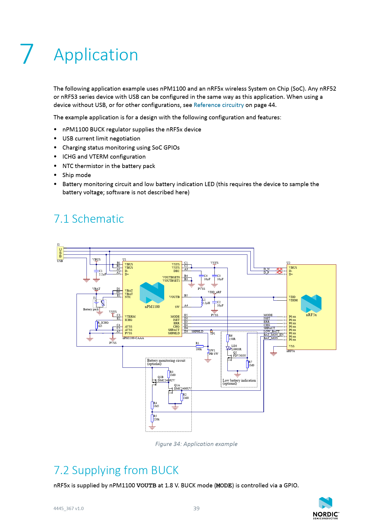
link to page 44 7 Application The following application example uses nPM1100 and an nRF5x wireless System on Chip (SoC). Any nRF52 or nRF53 series device with USB can be configured in the same way as this application. When using a device without USB, or for other configurations, see Reference circuitry on page 44. The example application is for a design with the following configuration and features: • nPM1100 BUCK regulator supplies the nRF5x device • USB current limit negotiation • Charging status monitoring using SoC GPIOs • ICHG and VTERM configuration • NTC thermistor in the battery pack • Ship mode • Battery monitoring circuit and low battery indication LED (this requires the device to sample the battery voltage; software is not described here) 7.1 Schematic J2 U S B USB VBUS U1 B1 VSYS U2 VBUS VSYS C1 B2 VBUS VSYS C2 VBUS A1 C1 D- DEC A3 D_N D- A2 2.2µF D+ D_P D+ VOUTBSET0 B4 C4 C3 VOUTBSET1 B3 10µF 10µF VBAT D1 VBAT PVSS D2 VBAT VDD_nRF E1 J1 NTC VOUTB B5 VDD L1 + VDDH 2.2µH C2 nPM1100 SW A4 10µF Battery pack VSYSC3 PVSS MODE nRF5x VTERM MODE E5 P0.xx E2 ICHG ISET D5 ISET P0.xx R_ICHG ERR E3 ERR P0.xx C4 1k5 AVSS CHG E4 CHG P0.xx C5 AVSS SHPACT D4 SHPACT P0.xx A5 SHPHLD LOW_BATT PVSS SHPHLD D3 TP1 P0.xx BAT_MON_EN R6 P0.xx nPM1100-CAAA BAT_MON 150R P0.xx PVSS R1 LD3 VSS 100k L0603R SW1 nRF5x Q2 PB SW FDV303N Battery monitoring circuit R7 (optional) 1M0 R3 1M0 Q1B DMC2400UV Low battery indication Q1A (optional) DMC2400UV R2 1M0 R4 1M5 R5 220k Figure 34: Application example 7.2 Supplying from BUCK nRF5x is supplied by nPM1100
VOUTB
at 1.8 V. BUCK mode (
MODE
) is controlled via a GPIO. 4445_367 v1.0 39 Document Outline Contents nPM1100 Feature list Revision history About this document 2.1 Document status 2.2 Core component chapters Product overview 3.1 Block diagram 3.1.1 In circuit configurations 3.2 System description 3.3 Power-on reset (POR) and brownout reset (BOR) 3.4 DPPM — Dynamic power-path management 3.5 Using Ship mode 3.6 Thermal protection 3.7 Battery considerations 3.8 Charging and Error LED drivers 3.9 System electrical parameters 3.10 System efficiency Absolute maximum ratings Recommended operating conditions 5.1 Dissipation ratings 5.2 WLCSP light sensitivity Core components 6.1 SYSREG — System regulator 6.1.1 USB port detection and VBUS current limiting 6.1.2 SYSREG resistance and output voltage 6.1.3 VBUS overvoltage and undervoltage protection 6.1.4 VBUS disconnect 6.1.5 Electrical parameters 6.1.6 Electrical characteristics 6.2 CHARGER — Battery charger 6.2.1 Charging cycle 6.2.2 Battery detection and UVLO 6.2.3 Termination voltage (VTERMSET) 6.2.4 Termination and trickle charge current 6.2.5 Charge current limit (ICHG) 6.2.6 Battery thermal protection using NTC thermistor (NTC) 6.2.7 Charger thermal regulation 6.2.8 Charger error conditions 6.2.9 Charging indication (CHG) and charging error indication (ERR) 6.2.10 DPPM — Dynamic power-path management 6.2.11 Electrical parameters 6.2.12 Electrical characteristics 6.3 BUCK — Buck regulator 6.3.1 Output voltage selection (VOUTBSET0, VOUTBSET1) 6.3.2 BUCK mode selection (MODE) 6.3.3 Component selection 6.3.4 Electrical parameters 6.3.5 Electrical characteristics Application 7.1 Schematic 7.2 Supplying from BUCK 7.3 USB port negotiation 7.4 CHG and ERR 7.5 Termination voltage and current 7.6 NTC configuration 7.7 Ship mode 7.8 Battery monitoring and low battery indication Hardware and layout 8.1 Ball assignments 8.2 Mechanical specifications 8.2.1 WLCSP 2.075x2.075 mm package 8.3 Reference circuitry 8.3.1 Configuration 1 8.3.2 Configuration 2 8.3.3 Configuration 3 8.3.4 PCB guidelines 8.3.5 PCB layout example Ordering information 9.1 IC marking 9.2 Box labels 9.3 Order code 9.4 Code ranges and values 9.5 Product options Legal notices

 Купить nPM1100-CAAA-R на РадиоЛоцман.Цены — от 53 до 408 ₽


