Datasheet IS2083 (Microchip) - 15
| Производитель | Microchip |
| Описание | Bluetooth Stereo Audio SoC |
| Страниц / Страница | 65 / 15 — IS2083. Device Overview. ...continued. IS2083BM Ball. IS2083BM-2L2 Ball … |
| Формат / Размер файла | PDF / 2.9 Мб |
| Язык документа | английский |
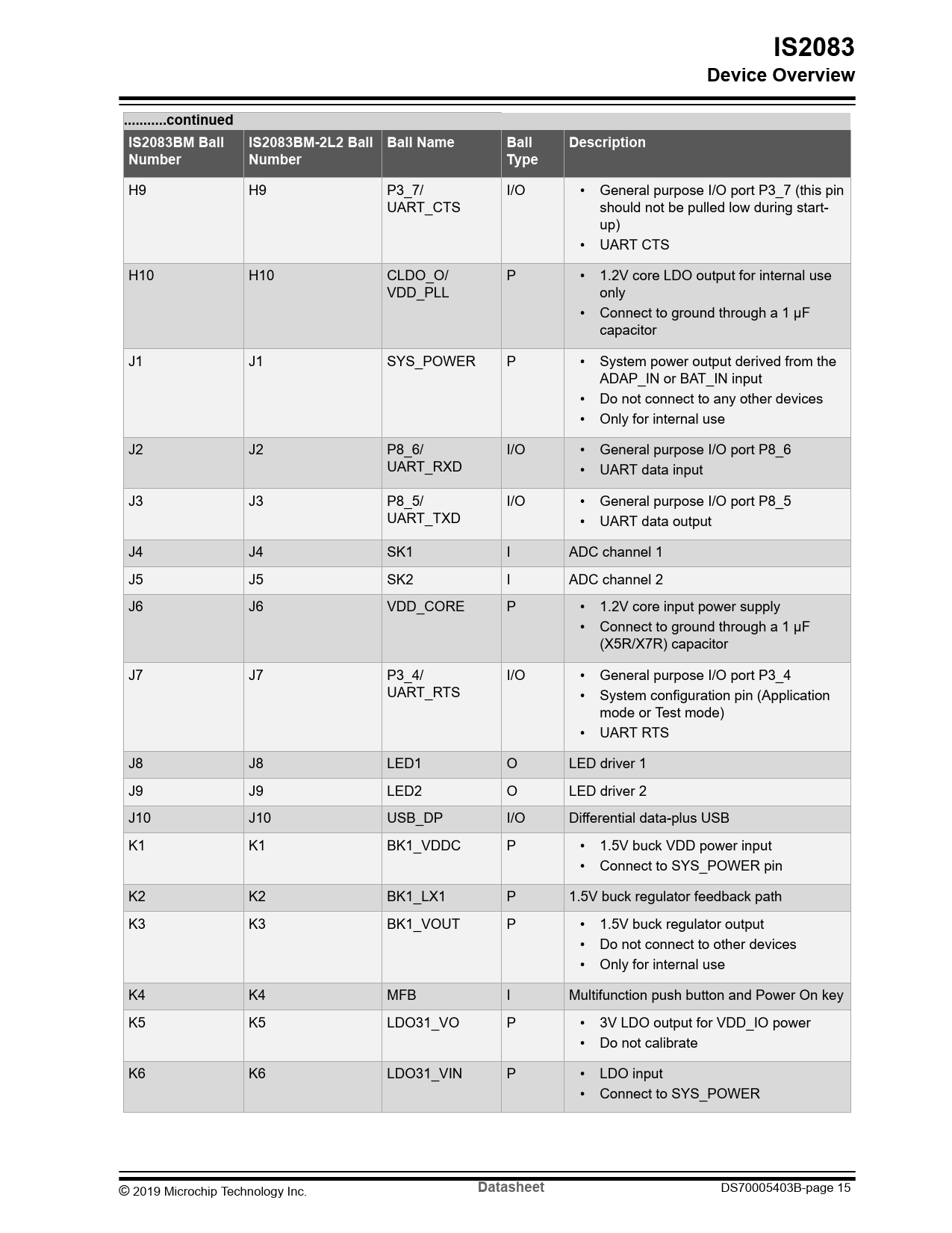
IS2083. Device Overview. ...continued. IS2083BM Ball. IS2083BM-2L2 Ball Ball Name. Ball. Description. Number. Type. Datasheet

Модельный ряд для этого даташита
Текстовая версия документа
IS2083 Device Overview ...continued IS2083BM Ball IS2083BM-2L2 Ball Ball Name Ball Description Number Number Type
H9 H9 P3_7/ I/O • General purpose I/O port P3_7 (this pin UART_CTS should not be pulled low during start- up) • UART CTS H10 H10 CLDO_O/ P • 1.2V core LDO output for internal use VDD_PLL only • Connect to ground through a 1 μF capacitor J1 J1 SYS_POWER P • System power output derived from the ADAP_IN or BAT_IN input • Do not connect to any other devices • Only for internal use J2 J2 P8_6/ I/O • General purpose I/O port P8_6 UART_RXD • UART data input J3 J3 P8_5/ I/O • General purpose I/O port P8_5 UART_TXD • UART data output J4 J4 SK1 I ADC channel 1 J5 J5 SK2 I ADC channel 2 J6 J6 VDD_CORE P • 1.2V core input power supply • Connect to ground through a 1 μF (X5R/X7R) capacitor J7 J7 P3_4/ I/O • General purpose I/O port P3_4 UART_RTS • System configuration pin (Application mode or Test mode) • UART RTS J8 J8 LED1 O LED driver 1 J9 J9 LED2 O LED driver 2 J10 J10 USB_DP I/O Differential data-plus USB K1 K1 BK1_VDDC P • 1.5V buck VDD power input • Connect to SYS_POWER pin K2 K2 BK1_LX1 P 1.5V buck regulator feedback path K3 K3 BK1_VOUT P • 1.5V buck regulator output • Do not connect to other devices • Only for internal use K4 K4 MFB I Multifunction push button and Power On key K5 K5 LDO31_VO P • 3V LDO output for VDD_IO power • Do not calibrate K6 K6 LDO31_VIN P • LDO input • Connect to SYS_POWER © 2019 Microchip Technology Inc.
Datasheet
DS70005403B-page 15 Document Outline Introduction Features Table of Contents 1. Quick References 1.1. Reference Documentation 1.2. Acronyms/Abbreviations 2. Device Overview 2.1. IS2083BM Device Ball Diagram 2.2. IS2083BM Device Ball Description 3. Audio Subsystem 3.1. Digital Signal Processor 3.2. Codec 3.2.1. Audio Performance 3.3. Auxiliary Port 3.4. Microphone Inputs 3.5. Analog Speaker Output 4. Bluetooth Transceiver 4.1. Transmitter 4.2. Receiver 4.3. Synthesizer 4.4. Modulator-Demodulator 4.5. Adaptive Frequency Hopping 5. Microcontroller 5.1. Memory 5.2. Clock 6. Power Management Unit 6.1. Device Operation 6.2. Power Supply 6.3. Adapter Input 6.4. Buck1 (BK1) Switching Regulator 6.5. Buck2 (BK2) Switching Regulator 6.6. Low-Droput Regulator 6.7. Battery Charging 6.7.1. Battery Charger Detection 6.8. SAR ADC 6.9. LED Driver 7. Application Information 7.1. Power On/Off Sequence 7.2. Reset 7.3. Programming and Debugging 7.3.1. Test Mode 7.3.2. Flash Memory and SQI Controller 7.3.2.1. SQI Controller 7.3.3. 2-wire Interface 7.3.3.1. Serial Program Clock 7.3.3.2. Serial Program Data 7.3.4. Enabling Programming Interface 7.3.5. On-chip Instrumentation 7.3.5.1. Enabling OCI Functionality 7.3.5.2. Entering Debug Mode 7.3.5.3. Reading the Debug Status 7.3.5.4. Reading the Program Counter 7.3.5.5. Stopping Program Execution (Entering Debug Mode) 7.3.5.6. Starting Program Execution (Exiting Debug Mode) 7.3.5.7. User Single Step Mode 7.3.5.8. OCI Single Step Mode 7.3.5.9. Setting Software Breakpoints 7.3.5.10. Simple and Complex Debug Triggers 7.3.5.11. Reading and Writing Memory/SFR Registers 7.3.5.12. Trace Buffer 7.3.5.13. Instruction Trace 7.4. General Purpose I/O Pins 7.5. I2S Mode Application 7.6. Host MCU Interface 8. Electrical Specifications 8.1. Timing Specifications 9. Package Information 10. Ordering Information 11. Document Revision History The Microchip Website Product Change Notification Service Customer Support Microchip Devices Code Protection Feature Legal Notice Trademarks Quality Management System Worldwide Sales and Service
 Купить IS2083BM-232 на РадиоЛоцман.Цены — от 86 до 1 237 ₽